Nogrid points release 6.9.0
April 2021
The release of NOGRID points 6.9.0 is available now.
This is new:
NOGRID Solver 6.9.0
- The multiphase part of the solver was redesigned and a lot of of new cases can be modeled now. We've added also a new multiphase case to the example list (see Multiphase Flow: a cleaning process).
- PUP foaming performance is increased up by the factor of 4. This is possible due to usage of a new Algebraic Multigrid Solver in combination with the new finite point organization which is fully parallelized. On Windows operation systems the computation time scales much more better with the number of CPU cores now. On Linux operation systems the computation time is still a little bit shorter compared to Windows systems.
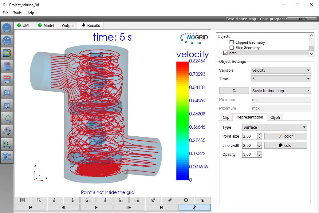
- The new Nogrid path integration tool computes path lines for stationary, transient and periodic flows. Nogrid path reads a selected set of time steps from a CFD simulation saved as an ENSIGHT result file. It produces path lines (time dependent flow tracers) which help to analyze the fluid dynamics. For more details please refer to the path tool pages.
- The time step size control for Euler point displacement models at inflow boundaries had a bug, effectively restricting the time step size to that of the Lagrange point organization.
- An approximation error in the application of CHAMBER_move has been removed. Before, the distance of two faces, one following the other by a CHAMBER_move statement, could slightly change. For example a small gap could form for two identical faces (created by a TWOSIDED alias line), one following the other.
- All move keywords are now supported for move statements referenced in a CHAMBER_move line.
- A new scheme to allow much larger time step sizes for models with free surfaces, which might become numerically unstable under the influence of gravity, has been added. The original keyword COEFF_dt_gravity for explicit time step control (possibly leading to unsatisfactorily small time steps) has been replaced by keywords STAB_Froude and STAB_Froude_fac, which enable and control the explicit time step control and the new implicit scheme.
- Arbitrary switches between prescribed movements (MOVE_position, MOVE_velocity, MOVE_rotation etc.) and FSI/rigid type movements (MOVE_rigid, MOVE_plunger) has been implemented. Time synchronization with a small time step should be used at times where such switches occur.
- The time integration for prescribed movements is now done with an adaptive refinement procedure to improve precision. In particular, time synchronization is not required anymore for precise integration if parameters (like velocity) rapidly change or if the kind of move changes (like from (MOVE_rotation, 0,0,0, 0,0,1) to (MOVE_velocity, 1, 0, 0)). Previously without synchronization and larger time steps, the integration of movements was imprecise in such situations.
- Expressions, equations and curves, which represent constants (like in are now evaluated at startup. As a consequence, the first column of curves can now contain such constant expressions. Arbitrary nesting of curves and equations is possible as long as no non-constant operations (like depvar{%ind_time%} for a curve or Y%ind_v(1)% or similar) occur.
- Integration and other evaluations in EVALUATE statements can now also be done by specifying the boundary condition name $bc_name$ (instead of $pp_name$ defined by POSTPROCESS$pp_name$). In particular this allows to integrate or evaluate functions on free surfaces.
- A new keyword restart_file for more sophisticated restart file selection has been introduced. This replaces the restart keyword.
- Internal data organization has been slightly reworked to open up the path for further optimizations and other improvements in point organization. A few optimizations have already been implemented providing some minor improvements.
- A new keyword BCON_CONTACT has been introduced. This allows to specify contact conditions in more complex models. For example if a material glass is in contact with two different mold or insulation materials and contact parameters depend on material specific properties, then this could not be specified by BCON_CNTCT.
NOGRID points GUI (Graphical User Interface)I
- The complete new path tool has been integrated within the GUI.
- The XML format has been re-formatted so that it can be read and viewed much more easier by many common text editors.
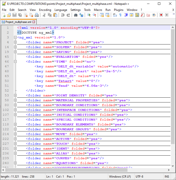
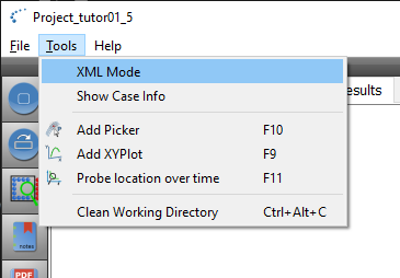
This XML will be a replacement for the current User file in future. Currently it is not used, but it is still saved to the disc. Internally the User file is converted to XML for viewing and editing. If the solver is executed the XML content is converted back to the User file format. The solver currently asks for the User file only. - Release 6.8.0 introduces an enhanced Graphical User Interface (GUI). Within this GUI the User can switch between working with the old files format and with the new XML format. If XML Mode is enabled the XML page is opened (see Figure 1) and the current User- and Settings file is converted to the XML format. If the project is saved then currently the old format is still used (so it converts the XML file into the old User- and Settings file).
- The new integrated XML editor (see image below) shows the tree items graphically and the User can change the items properties directly by double click on the corresponding item.
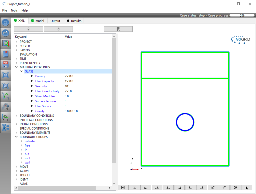 Figure 1: New XML GUI
NOGRID preprocessor COMPASS
-
We've fixed the Undo/Redo bug: In cases the Undo was used, not all objects where deleted correctly and did still exist within the object tree. This did lead to a crash if the selection tool tries to access all objects.
-
The window view direction was unified and the rotate +90° and rotate -90° button was added

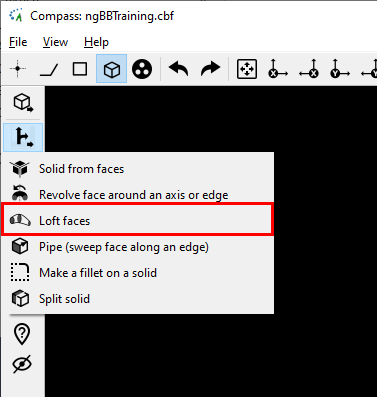
- Loft wires and loft faces feature was added
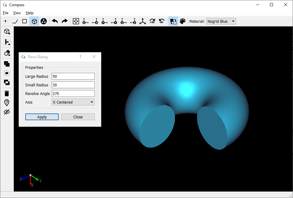
- The User can now create a torus (=>Volume mode-> 3D Primitives) specifying a revolving angle
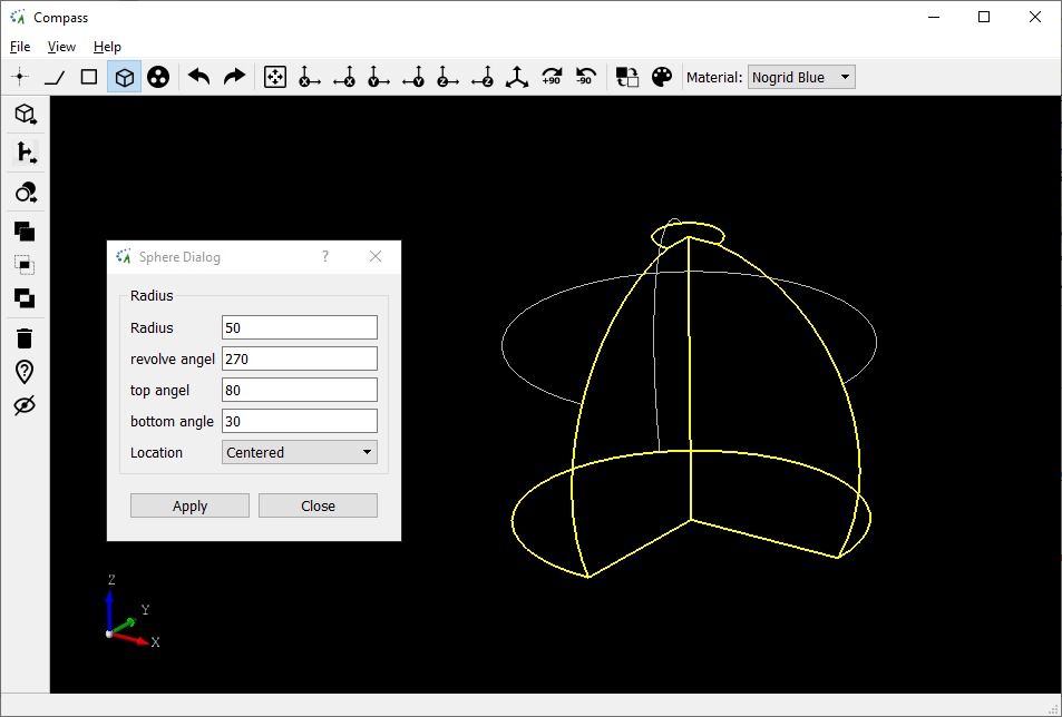
- The sphere dialog was extended to create more flexible 3D parts. The User can define the radius of the sphere, the revolve angle and two angles to top and bottom cut plane:
- We've replaced all colored icons by the unified clear black/white icons.
- Compass can generate small wrong orientated mesh triangles. Compass now deletes these degenerated triangles automatically.
- The reduced (collapsed) mesh can now be viewed directly after meshing the faces. In the figure below a collapsed mesh is shown. The edge length of the square is 10 mm and the mesh size is 0.5 mm. The meshing algorithm first meshes the face regular with triangles of average length of 0.5 mm and the mesh collapsing method tries to collapse all triangles within the face taking into account the local curvature. The boundary triangles will not changed.
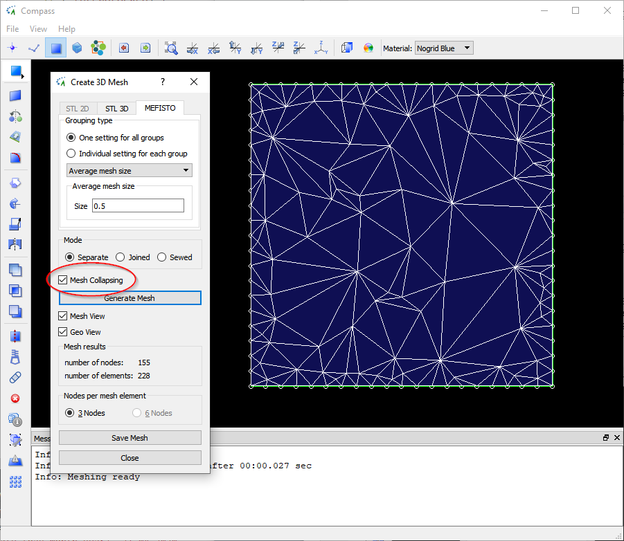 Figure1: View of the mesh collapsing method