Container Forming Simulation Case Study
Gerresheimer provides a wide range of different containers, varying in shape, weight and color. Having been issued with these parameters by their customers, the questions remain as to whether a specified container is producible or needs to be optimized further. For that reason Gerresheimer uses Nogrid software successfully for satisfying their customers’ expectations for lightweight but stable products.
Nogrid provides glass forming simulation software developed especially for the container glass industry. Nogrid software computes glass forming processes in 2-D (axis-symmetric), 3-D-part (cut 3-D model) and full 3D and allows simulating all kinds of glass forming processes, amongst others for container glass:
- BB (Blow and Blow)
- PB (Press and Blow or Wide Mouth PB)
- NNPB (Narrow Neck Press and Blow)
As representation for all these processes Figure 1 shows schematically the process steps that occur during the BB process.
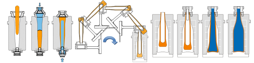
Figure 1: Schematic steps during BB process
After gob loading air blows a cavity into the molten glass gob which rests in the blank mold of the forming machine. The parison (the glass gob at the end of the first blow) is moved from the blank to the final mold. In the final mold air is used to blow the container into its final shape.
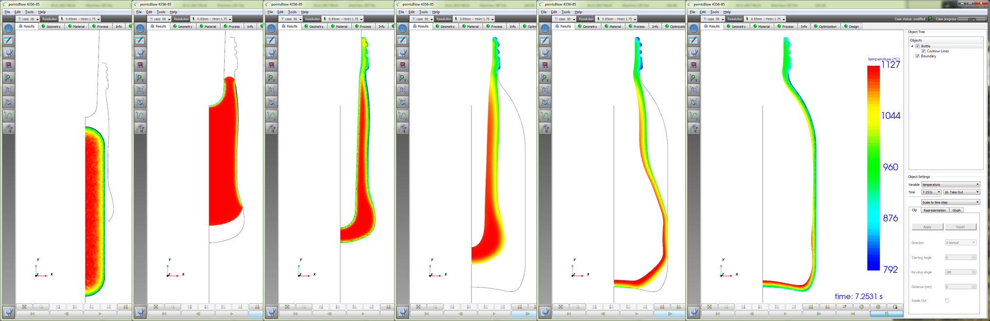
Figure 2: Some NNPB steps for Gerresheimer 4356 container
As in reality the simulation starts with gob loading and ends at take out. All process steps are integrated in one simulation model and all walls (representing the plunger and the molds) are switched on and off at the corresponding time step given by the IS machine time data.
The shape of the glass container can be each possible 3-D shape. Also containers with a handle can be computed. Thus there are no limits regarding container design and the User can test and evaluate a certain container without restrictions.
Some of Gerresheimer containers
The focus in this paper is on computing the wall thickness distribution and comparing it with the real container. The container investigated in this paper is a 100 g container produced by the narrow neck press and blow process. The computation time depends on gob weight, on resolution and on the dimension (2-D or 3-D) and can rise from 10 minutes up to 12 hours (it depends in addition on the computer power, of course). These short computation times are noticeably, so the User can run several container cases per day. For this axis-symmetric (2-D) container the computation time was about 10 minutes.
Geometry
Because all companies use their own CAD (Computer Aided Design) system for modeling the molds and all other parts, Nogrid pointsBlow can import all shapes required using the well-known STEP interface.
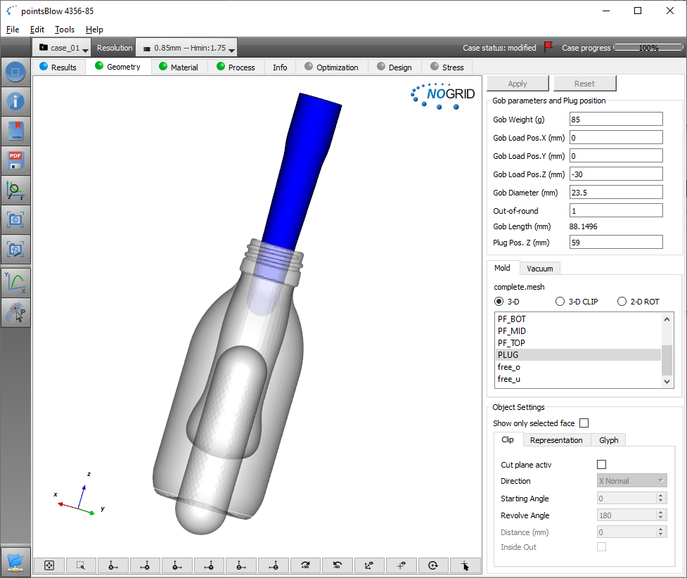
Figure 3: Geometry view Gerresheimer 4356 container
That means the User can simply extract the shapes required into one CAD file and export this file into the STEP format[1]. If all material properties and process properties are given, the User can start the computation immediately. There is no meshing required and the points within the initial gob are filled automatically.
[1] Usually all CAD packages support exporting to the STEP format.
Material properties and process data
In container glass industry the glass composition and therefore the glass properties can vary, but usually soda lime glass is used. For that reason the User can set all properties required. The most important and most sensible material property for the forming process is the viscosity of the glass, which depends on the temperature of course. For that reason it is important to set the temperature for the initial glass gob precisely. Unfortunately the temperature of the initial gob is usually unknown and can be measured only with huge measurement effort. But good news is that the Nogrid pointsBlow software can determine the initial gob temperature automatically by the given gob weight using an empirical law which was found during a project where more than 30 bottles were investigated.
Results
In order to analyze the results Nogrid pointsBlow computes the thickness of the walls at each time step by solving an additional differential equation.
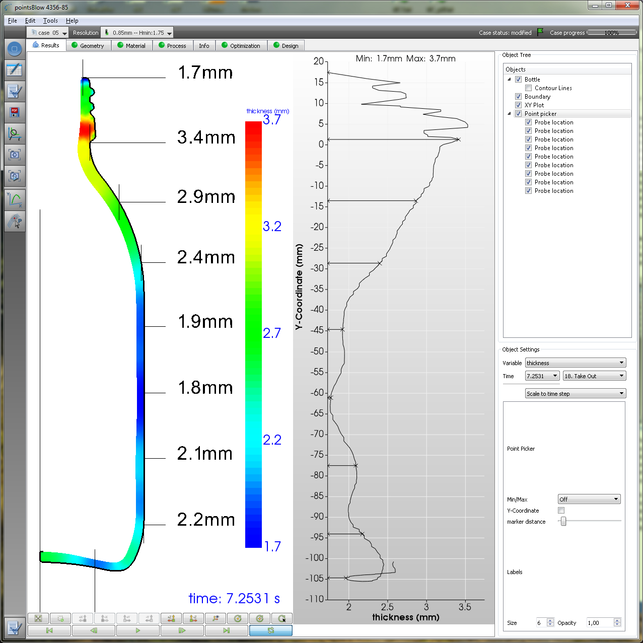
Figure 4: Thickness [mm]: 3D view, xy-plot and point probing
The User can select the thickness distribution like a variable such as for instance the temperature (see Figure 4). The xy-plot displayed in Figure 4 shows the thickness distribution over the height of the bottle. In addition the User can select certain points within the glass volume and the software probes and displays all variables at that position.
As shown in Figure 5 the agreement between simulation and experiment is quite good. We used Gerresheimer container glass properties for the computation. The solid blank mold, the solid blow mold and the solid plug are replaced by an approximate heat flux boundary condition
Q = h A ( Tglass-Tmold )
h is the heat transfer coefficient, Tglass is the glass temperature at the interface glass-mold and Tmold is the temperature of the mold.
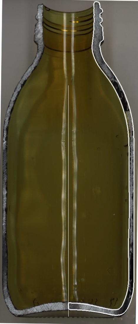
Figure 5: White line shows computed thickness
The heat transfer coefficients h are constant over time for this container and only the blank mold heat transfer coefficient needs to be adjusted in order to get appropriate results.
The User can analyze the movement of a certain volume, from the blank mold to the final mold in detail. As shown in Figure 6 he can immediately answer the question which glass particle of the blank mold has moved to which position in the final mold. With this information the origin of thin wall thickness areas can be identified and improved in the blank mold geometry.
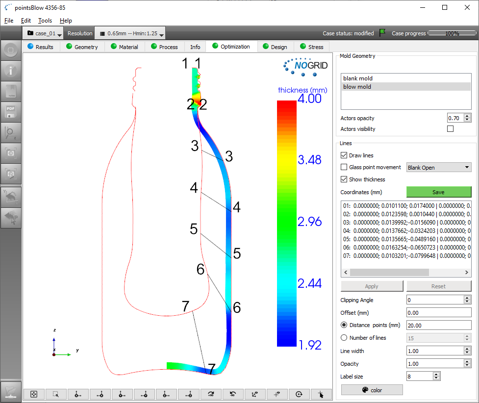
Figure 6: Movement from blank to blow mold
Gerresheimer uses simulation with great benefits. Nogrid software computes the forming processes using all IS machine time data including pressure data, plunger movement and heat transfer data. IS time machine settings can improve or worsen the quality of the thickness distribution. So Nogrid software helps Gerresheimer with:
- Finding the optimal blank mold shape
- Reducing the number of mold design tests
- Finding the best IS time machine data
- Reducing the number of trials in production
- Finding the lowest possible container weight
- Avoiding weaknesses in the container
- Shortening the development times
Last but not least the software helps identifying the origin of a certain glass defect in the container. Therefore the simulation helps to understand how the forming process is working in detail which is the basis for all improvements.
Summary
Nogrid pointsBlow software allows all main glass container forming processes to be simulated in 2-D or full 3-D and in a practicable time. The graphical user interface is designed especially for the glass container industry and all modeling and simulation steps are easy to understand and perform.
By using the software, the number of mould and production design trials can be reduced significantly and the ROI can already be achieved after the first new bottle design. For Gerresheimer Nogrid pointsBlow has become an indispensible tool as part of the continuous improvement process.
Stärken der Nogrid Software
Unsere Stärke ist das schnelle Preprocessing, da unsere Software auf einer gitterfreien Methode basiert - es muss kein Netz für das Fluidvolumen in 3D oder für die Fluidfläche in 2D generiert werden. Dies führt zu einer besonders kurzen Modellierungszeit (auch für komplizierte Modelle), so dass Sie im Vergleich zu gitterbasierten CFD-Softwareprodukten viel Zeit sparen können. Die gitterfreie Methode ist stark bei der Berechnung von bewegten Teilen oder bei der Berechnung von komplexen freien Oberflächen.
Wie Sie im Bild unten sehen können, benötigt man für die Ränder der Geometrie nach wie vor ein Netz, damit die inneren finiten Punkte den Rand detektieren können. Die Ränder müssen also vernetzt werden und die finiten Punkte im Inneren werden während der Simulation automatisch generiert.
Wie Sie im Bild unten sehen können, benötigt man für die Ränder der Geometrie nach wie vor ein Netz, damit die inneren finiten Punkte den Rand detektieren können. Die Ränder müssen also vernetzt werden und die finiten Punkte im Inneren werden während der Simulation automatisch generiert.
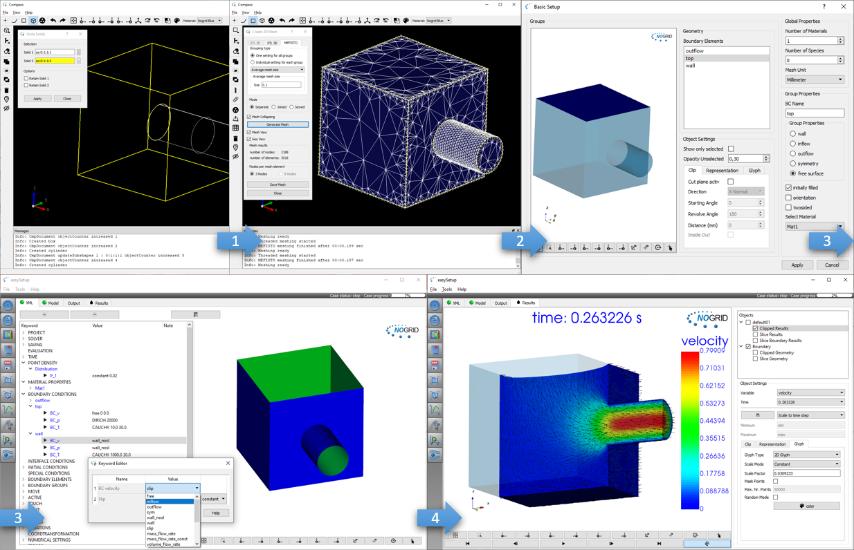
Einfache und schnelle Modellierung: Geometrie erzeugen und Ränder vernetzen, Fall aufsetzen und Simulation starten
Was kann die NOGRID Strömungssimulationssoftware für Sie tun?
Verlässliche industrielle Prozesse sprechen für sich und sind verantwortlich für den Erfolg eines Unternehmens. Für viele Prozesse spielt das Strömungsverhalten des Fluids eine wichtige Rolle für den Erfolg. Da industrielle Designs oft sehr komplex sind, gibt es verschiedene Faktoren, die in Fluidströmungs-Anwendungen wichtig sein können. Durch eine CFD-Simulation mit einer professionellen Software können Sie Ihre Prozessleistung simulieren und relevante Parameter berücksichtigen: Die Anwendung von NOGRIDs numerischer Strömungssimulationssoftware ermöglicht es Ihnen, die Fluidströmung, den Wärme- und Massenübergang sowie eventuell stattfindende chemische Reaktionen vorherzusagen, zu analysieren und zu kontrollieren und gibt Ihnen die Möglichkeit, Ihre Prozessleistung zu optimieren. Dadurch erhalten Sie eine Basis für bessere Design-Entscheidungen.
Die Strömungssimulationssoftware von NOGRID ist ein gitterfreies Tool mit erstaunlicher Flexibilität, Genauigkeit, Zuverlässigkeit und Robustheit. Die Software liefert qualitativ hochwertige Ergebnisse für ein weites Feld von Fluidströmungs-Anwendungen.
Warum sollten Sie sich für NOGRID Strömungssimulationssoftware entscheiden?
Zusätzlich zum Testen und Experimentieren hilft die NOGRID Strömungssimulationssoftware, die Bewertung Ihres Designs zu verbessern und den Erfolg Ihres industriellen Prozesses zu steigern. Zu lernen, wie sich die Fluidströmung verhalten wird und wie sicher industrielle Prozesse oder Prozessschritte funktionieren, lässt Ihr Wissen von Simulation zu Simulation wachsen. Sie bekommen ein besseres Verständnis für Ihre Prozesse, was wiederum zu enormen Einsparungen von Herstellungskosten und - zeit und gleichzeitig zu einem Endprodukt von hoher Qualität führt. Durch Simulation erhalten Sie bessere Konstruktions- und Betriebsparameter, steigende Planungssicherheit und Sie sparen Zeit und Geld dadurch, dass Sie Ihr Produkt schneller auf den Markt bringen können.
Training
In unserem zwei-Tage Trainingskurs werden Sie lernen, wie man die NOGRID CFD/CAE Software effizient einsetzt. Unser technischer Support hat Erfahrungen in vielen Disziplinen und kann Ihnen zeigen, wie man schwierige Fälle bewertet, behandelt und löst.
Für mehr Details bitte hier weiterlesen: Trainingskurse →
Technischer Support
Wir bieten den kompletten technischen Software Support an. Von der ersten Minute an, ab der Sie die Software nutzen, können Sie uns über Telefon oder E-Mail erreichen. Schreiben Sie uns, wir sind Ihnen gerne behilflich.
Für mehr Details bitte hier weiterlesen: Software Support →
Service
Oft sind Zeit und Ressourcen knapp bemessen, so dass die Vergabe von Simulationsaufgaben eine attraktive Möglichkeit sein kann, um schnell und kostengünstig anstehende Aufgaben zu bearbeiten. Basierend auf unserem Know-how können wir eine Fülle von Serviceleistungen auf dem Gebiet der Simulation von Strömungen anbieten.
Wir modellieren und entwickeln für Sie. Sie brauchen hierfür keine NOGRID-Software Lizenz zu kaufen. Wir bieten Ihnen einen individuellen Berechnungsservice für Ihre Verfahren und Prozesse an, der genau auf Ihre Wünsche zugeschnitten ist.
Für mehr Details bitte hier weiterlesen: Simulation Services →