Simulation Blow Molding Plastic Tank
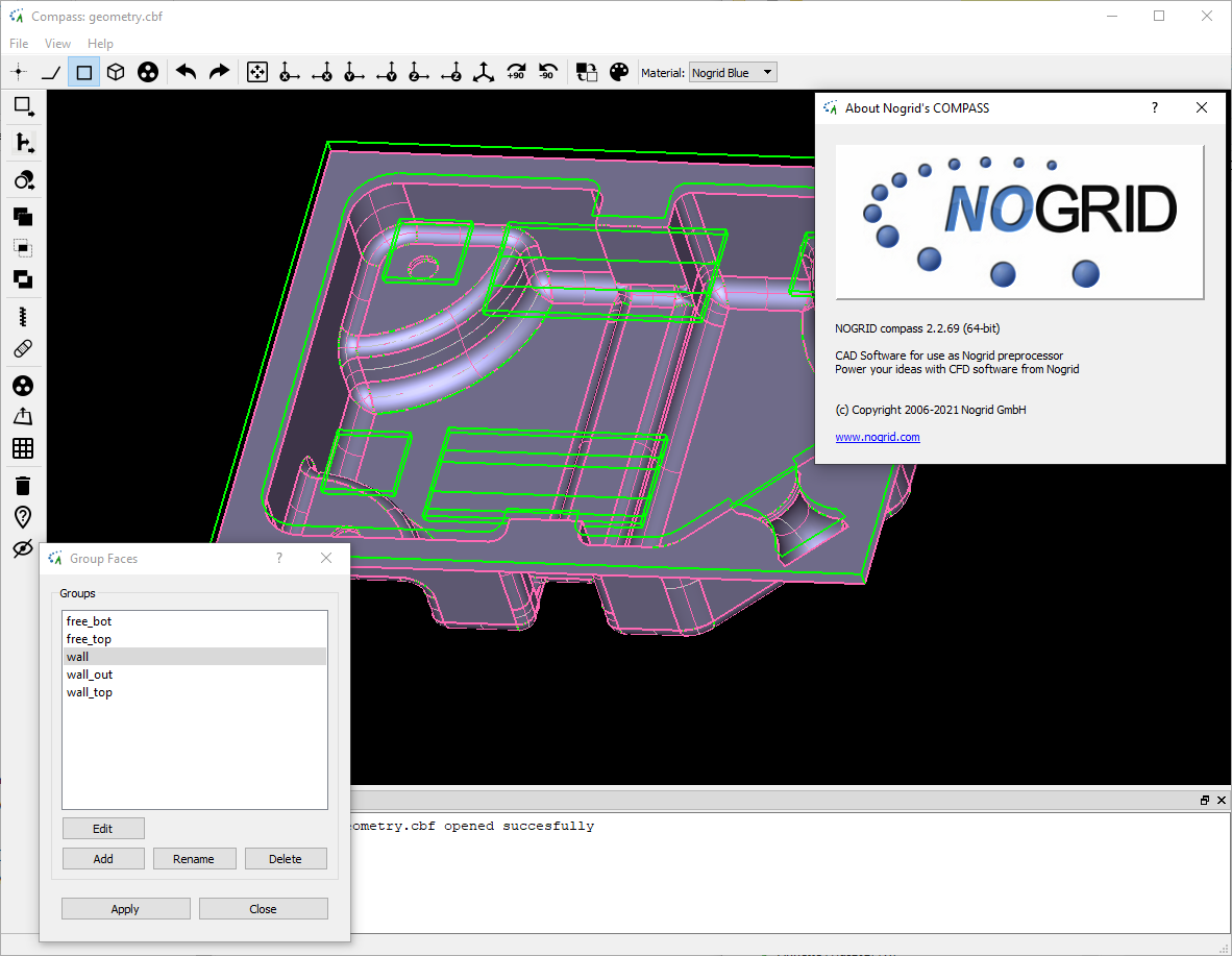
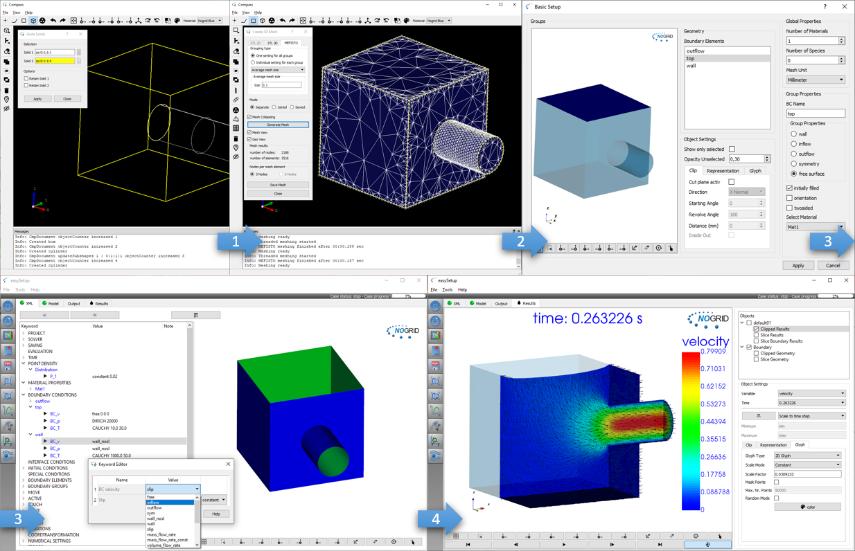
Figure 1: CAD model created in NOGRID's COMPASS
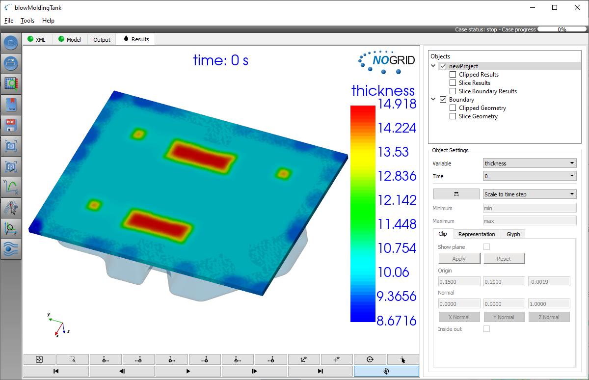
Figure 2: Initial extruded flat parison with variable thickness distribution in full 3-D (no shell elements)
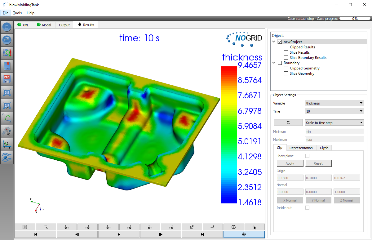
Figure 3: Extrusion blow molding process in full 3-D (no shell elements) using a flat parison with variable thickness
Figure 4: Animation of the extrusion blow molding process in full 3-D
Simulation of blow molding of plastic tanks using our meshless CFD software NOGRID points will move you into the world of real 3D simulations. Based on the geometrical model which can either be imported from your CAD or created with our CAD preprocessor COMPASS you can generate a computer model of a tank in a very short time compared to mesh-based methods.
Figure 1 on the left side shows a geometry built in COMPASS. To use the geometry within the fluid simulation (only) the walls need to be meshed. For 3D simulations this is a surface mesh and for 2D simulations it is a line mesh. The meshing can be done in COMPASS using also enhanced features like for instance the mesh collapsing technique.
Understanding blow molding processes
Fuel tanks made by plastics allow for weight reduction and high accuracy in comparison to steel tanks and they are free in design to fit into given space. The blow molding allows to produce tanks with complex geometry. The challenges are the stability under pressure, the integration of internal components and the chemical resistance against the fuel. A key question in the tank design is the wall thickness of the tank. It is a result of the initial thickness of the plastic parison and the flow properties of the melted plastic.
Three main types of blow molding are widely used
- Extrusion blow molding
- Injection blow molding and
- Injection stretch blow molding
and in this article we present an extrusion blow molding process in full 3D by which two (initially flat) plastic parts are formed and joined together later. Forming means that the flat parison of variable thickness is blown into a cavity and held there until it is sufficiently cool. NOGRID points can help to understand all phases of the blow molding process, beginning with the clamping (or pressing) of the sheet in the tool, the pressure loading, the first touch of the sheet at the wall and the final stretching to all corners of the tank geometry.
Capabilities of NOGRID points software
NOGRID unites abilities to handle free surface flow and moving parts in the domain and allows the simulation of any conceivable mold geometry and operation modes such as
- blow sheets with individual thickness distribution
- computation is in full 3D solving complete Navier-Stokes-Equations
- moving of the middle part (for clamping or pressing)
- free definable material properties by equations or curves
- large tank geometries with small gaps or cutouts and
- open or closed molds including moving of the middle tool (plunger)
Nogrid's strengths
Easy and fast modelling: Build geometry, mesh boundary, setup the case and start computation
What is CFD from NOGRID?
CFD solves the fundamental equations that define the fluid flow process. With CFD software from NOGRID every engineer makes better decisions by predicting, analyzing and controlling fluid flow, heat and mass transfer or chemical reaction. By using NOGRID software for flow modeling you receive information on essential flow characteristics as for example flow distribution. Using it additional to testing and experimentation NOGRID software helps to improve the evaluation of your design – resulting in better construction and operation parameters, increasing planning security and money savings due to faster time to the marketplace for your product or process.
Choose NOGRID
With NOGRID, you choose professional CFD software and services – our aim is helping you to be successful. When you decide to work with NOGRID you choose close cooperation with a dynamic, flat hierarchies-organization. Short information channels result in quick and accurate professional support and service. Our team consists of highly qualified employees, who are experts in fields such as numerical simulation or computational fluid dynamics. Based on our know-how, we are pleased to offer the following services, responding to your individual requirements:
TRAINING
In our two-days training courses you will learn, how to use NOGRID CFD software efficiently. Our technical support team will teach you how to handle and solve different cases.
For more details please refer to Training Courses →
Technical Support
We offer full professional support from the minute you start using our software, by telephone or by email. Contact us, when ever needed.
For more details please refer to Software Support →
Service
Lack of time or resources and other constraints often make outsourcing an attractive solution. We help you with your flow modeling needs. Based on our engineering expertise in this field we offer individual numerical simulation services matching the unique needs of your organization.
For more details please refer to Simulation Services →