How to Start Container Forming Simulation
The prediction of the thickness distribution of any desired glass container by computer simulation is of great demand in the glass container industry as production trials can be reduced significantly. For optimal using the simulation tools should be integrated within the production workflow and it has been shown that companies need to introduce the software in 3 steps: proof-of-concept phase, pilot phase and production phase.
Nogrid provides forming simulation software developed especially for the container and tableware glass industry. Nogrid software computes glass forming processes in 2-D (axis-symmetric), 3-D-part (cut 3-D model) and full 3-D and allows simulating all kinds of glass forming processes, amongst others for container and tableware glass:
- BB (Blow and Blow)
- PB (Press and Blow or Wide Mouth PB)
- NNPB (Narrow Neck Press and Blow)
- PB (tableware)
Nogrid pointsBlow solves the complete Navier-Stokes equations (continuity equation, velocity equations and energy equation) within the fluid. The glass viscosity depends on temperature. The User can add new glass compounds and set all material properties individually.
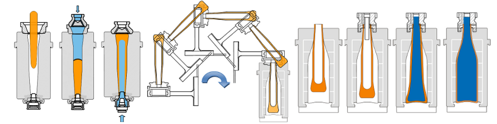
Figure 1: Steps during Blow and Blow (BB) process
The initial gob geometry is variable and the complete gob loading process is included within the simulation. If required a funnel can be added. In case of PB or NNPB the plug movement is controlled by a time-position curve or by force. Figure 1 shows schematically the process steps that occur during the BB process. The User can set the IS machine data easily within the GUI for all wall types and all thermal conditions as well.
The container geometry is created in a CAD (Computer-Aided Design) system. The market for CAD software is huge and in most cases CAD vendors use their own format for saving and interchanging the data. Providing and maintaining all these formats turns out to be profitable, but fortunately all CAD packages support the well-known STEP format to exchange the data between different CAD systems. The Nogrid software can import the STEP file including all face names. This is very important, because in that case the Nogrid software can connect all faces with the corresponding initial, boundary and move conditions and run the simulation without any additional user interaction.
If the User decided to investigate a modified geometry only the geometry has to be replaced. All other input data can be reused. Once the 3-D CAD geometry is imported the User can simply select the geometrical dimension of the model. That means the User is able to run the simulation in 2-D (axis-symmetric), 3-D part or full 3-D without changing the CAD geometry or modifiying the simulation conditions.
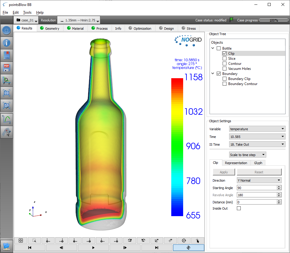
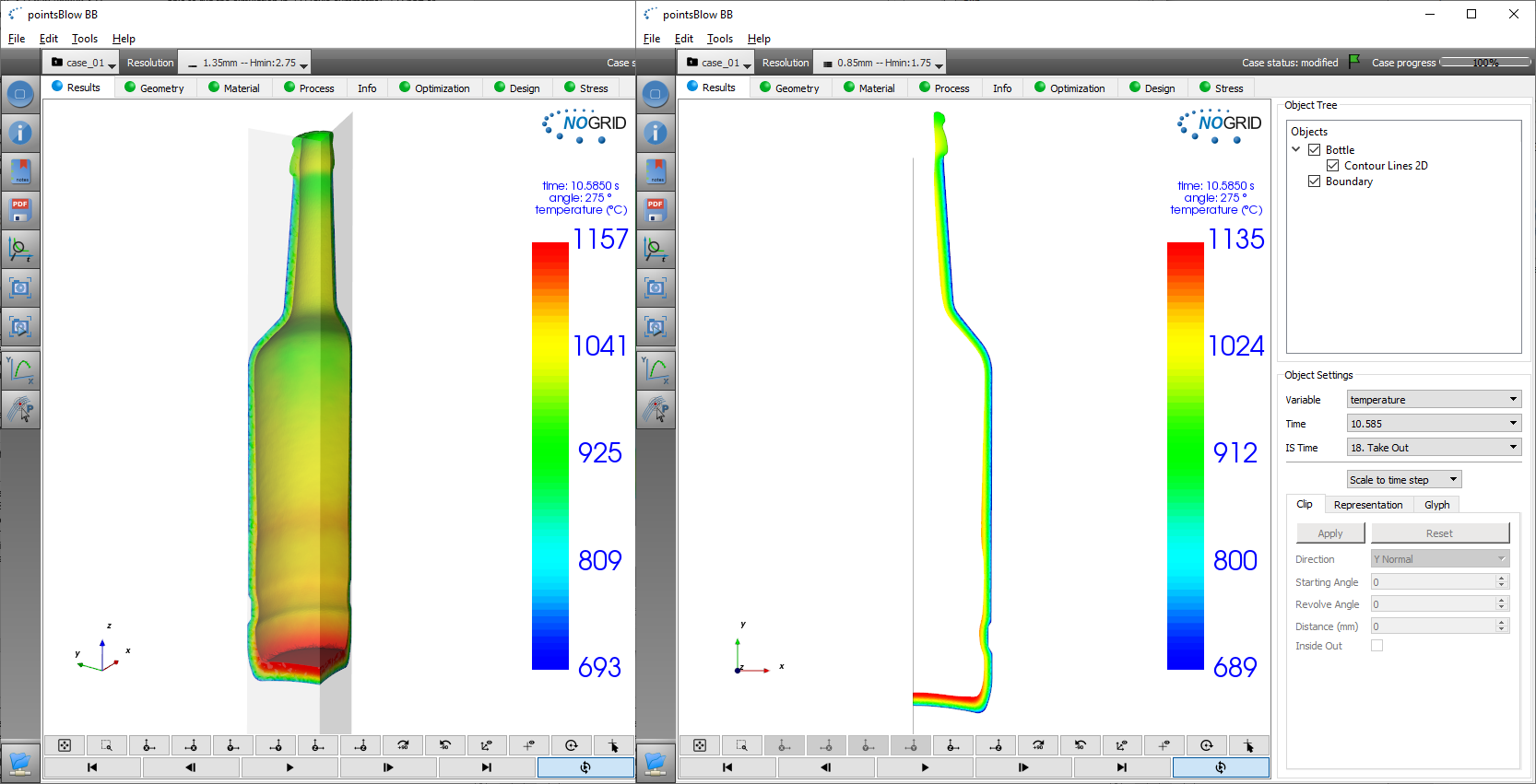
Figure 2: Results 3-D, 3-D-clip and 2-D (axis-symmetric)
As one can imagine the shape of the bottle can be each real 3-D shape. Also bottles with a handle can be computed. Thus there are no limits regarding bottle design and the User can test and evaluate a certain container without restrictions.
How to introduce and use the simulation software?
As glass container makers know, a lot of parameters and conditions influence the final thickness distribution of a container. For example if the glass viscosity is not known exactly, the results of the simulation can vary a lot.
The same is valid for the initial gob temperature. From a practical point of view it is not possible to measure the temperature of the gob completely. Companies are trying to measure the gob temperature in large research projects (sometimes in cooperation with other companies, because of the development of measurement techniques). But the temperature fluctuating is still about 50 °C. For simulation we need +-5 °C.
Furthermore the influence of the type of and the amount of swabbing compounds used on friction and heat flux is huge and measuring the data is practically not possible. For all these reasons the engineer has to make assumptions for the simulation and prove and adapt the simulation results by experiment.
To introduce the simulation software within a company usually 3 steps are required:
- Proof-of-concept phase
- Pilot phase
- Production phase
One of the ways to do a proof-of-concept is to select a sufficient number of well known containers as benchmark and compute these containers with the new simulation tool. The number of containers to be investigated in this phase depends on the branche, but should not be lower than 5. Due to the complex shapes in the parfume branche certainly more tests are required. This first phase will use the simulation tool on a small scale, with sufficient time to explore different ways in which it can be used. Objectives should be set for this proof-of-concept phase in order to accomplish what is needed within the current organizational context.
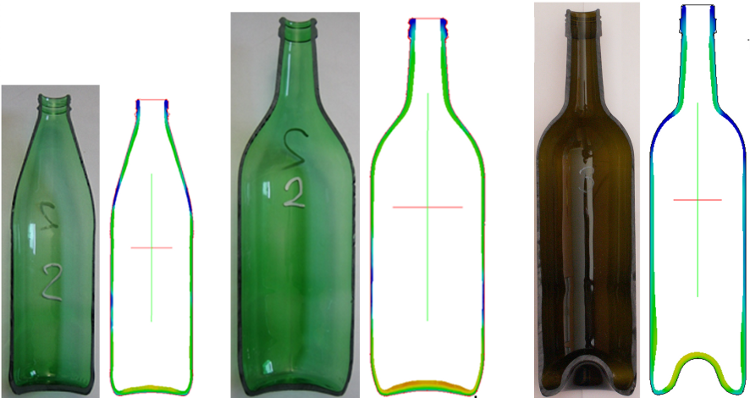
Figure 3: Phase 2: Most unknowns are estimated
In the second phase, the pilot phase, one or more qualified designers/engineers start to evaluate the simulation software in the inhouse production environment. A typical workflow is shown in Figure 4. The simulation starts after the first trial and the Users try to find best agreement between experiment and simulation:
- Manufacture the molds for the new container
- Perform a production trial
- Compute the container by adapting the properties and the conditions until you reach best agreement between simulation and reality
After step 3 the User can start to change the blank mold design and prove it by simulation. If a good shape is found the real blank mold can be modified.
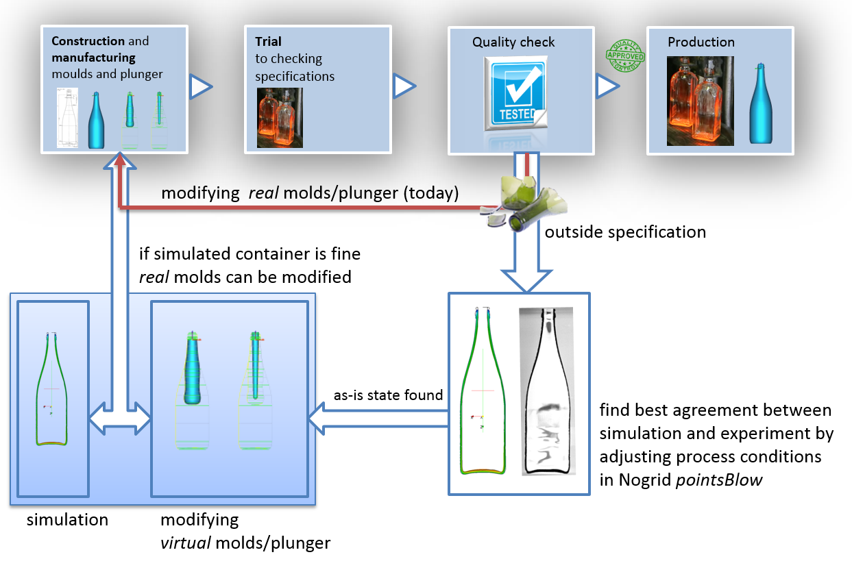
Figure 4: Workflow during the software pilot phase
Most unknown conditions and properties are found in this pilot phase. Furthermore a pilot phase is expected to have issues or problems – they should be solved in ways that can be used by everyone later on. The pilot project should experiment with all kinds of different containers produced at different locations in order to include all possible conditions within the settings. The objectives for a pilot project for a new tool are:
- To learn more about the tool in detail and estimate and evaluate unknown conditions and material properties
- To see how the tool fits real glass containers
- To decide on standard ways of using the tool that will work for all potential users
- To evaluate the pilot project against its objectives (have the benefits been achieved at reasonable cost?).
Finally, if the pilot phase is successfully finished one can start the third phase – the production phase. In this phase the software is made available out to all designers in order to optimize a certain container or simply to check if a new unknown container will produce difficulties or simply work well without doing anything before going into production.
Summary
Nogrid software is able to compute any desired glass container in full 3-D, in a 3-D part or in 2-D (axis-symmetric) in a very practicable time. From our experience, depending on the engineering power, number of users and number of trials required, the time from first proof-of-concept phase to the production phase can take 6 months up to 2 years. Nogrid is prepared to support interested companies through all steps required.
Nogrid's strengths
Particular strengths of NOGRID's fluid flow CFD software are the rapid preprocessing (no fluid grid needs to be generated, only the boundary mesh, inner finite points are generated automatically depending on User setting initially and during computation), and the outstandingly short computation time even for complicated cavities.
As you can see in the image below, the boundary of the geometry still requires a mesh to allow the interior finite points to detect the boundary. The boundary must therefore be meshed and the finite points inside are automatically generated during the simulation controlled by User specifications.
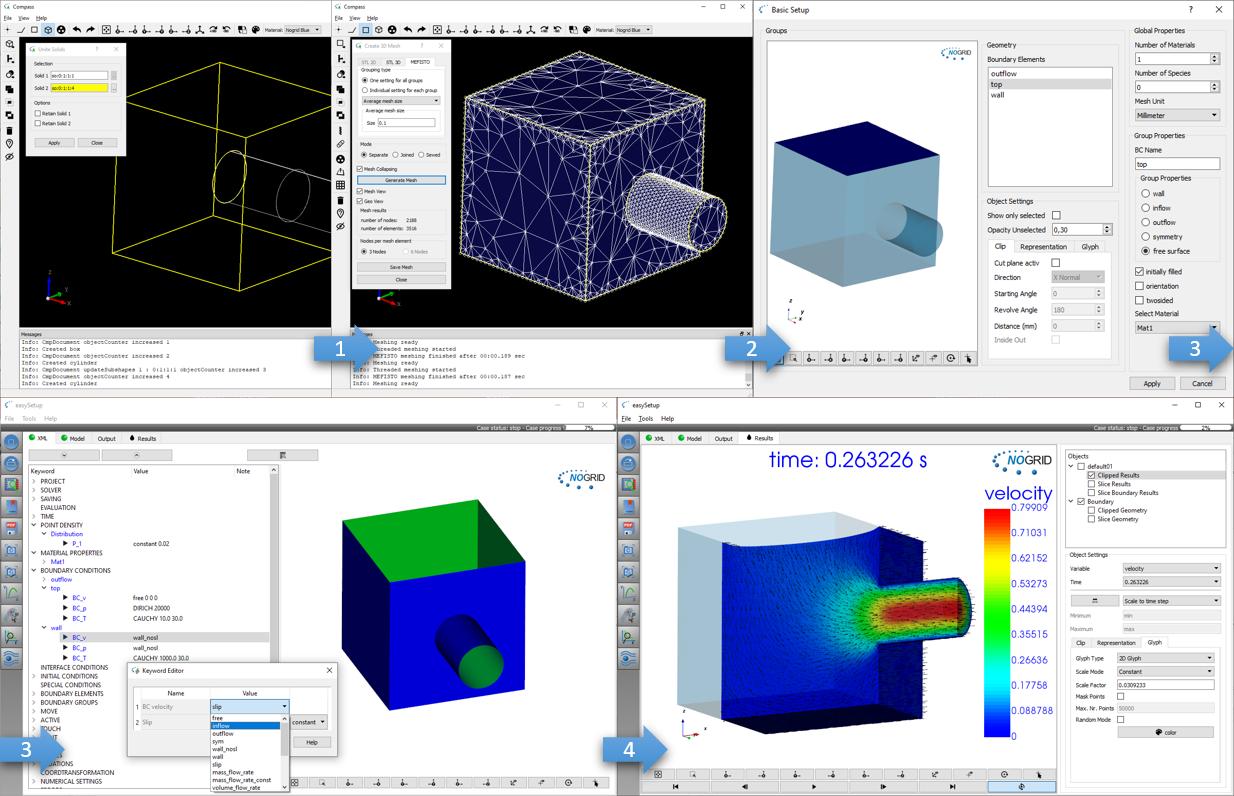
Easy and fast modelling: Build geometry, mesh boundary, setup the case and start computation
What is CFD from NOGRID?
CFD solves the fundamental equations that define the fluid flow process. With CFD software from NOGRID every engineer makes better decisions by predicting, analyzing and controlling fluid flow, heat and mass transfer or chemical reaction. By using NOGRID software for flow modeling you receive information on essential flow characteristics as for example flow distribution. Using it additional to testing and experimentation NOGRID software helps to improve the evaluation of your design – resulting in better construction and operation parameters, increasing planning security and money savings due to faster time to the marketplace for your product or process.
Choose NOGRID
With NOGRID, you choose professional CFD software and services – our aim is helping you to be successful. When you decide to work with NOGRID you choose close cooperation with a dynamic, flat hierarchies-organization. Short information channels result in quick and accurate professional support and service. Our team consists of highly qualified employees, who are experts in fields such as numerical simulation or computational fluid dynamics. Based on our know-how, we are pleased to offer the following services, responding to your individual requirements:
TRAINING
In our two-days training courses you will learn, how to use NOGRID CFD software efficiently. Our technical support team will teach you how to handle and solve different cases.
For more details please refer to Training Courses →
Technical Support
We offer full professional support from the minute you start using our software, by telephone or by email. Contact us, when ever needed.
For more details please refer to Software Support →
Service
Lack of time or resources and other constraints often make outsourcing an attractive solution. We help you with your flow modeling needs. Based on our engineering expertise in this field we offer individual numerical simulation services matching the unique needs of your organization.
For more details please refer to Simulation Services →