Practical Container Forming Simulation
In order to use simulation in manufacturing environments it is very important to integrate the simulation tools within the production workflow. Usually all companies use a professional CAD system and therefore all simulation tools must be able to interact easily with these systems. Furthermore the forming simulation must be able to compute the containers in 2-D (axis-symmetric), 3-D-part and full 3-D depending on the geometrical properties and switching the geometrical dimension should be no issue.
Nogrid provides forming simulation software developed especially for the container glass industry. Nogrid software computes glass forming processes in 2-D (axis-symmetric), 3-D-part (cut 3-D model) and full 3-D and allows simulating all kinds of glass forming processes, amongst others for container glass:
- BB (Blow and Blow)
- PB (Press and Blow or Wide Mouth PB)
- NNPB (Narrow Neck Press and Blow)
Nogrid pointsBlow solves the complete Navier-Stokes equations (continuity equation, velocity equations and energy equation) within the fluid. The glass viscosity depends on temperature as shown in Figure 1. Three standard viscosity curves are implemented and further curves can be added by the User.
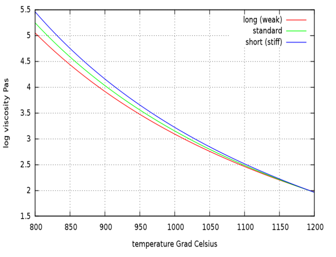
Figure 1: Viscosity depends on temperature
In the container glass industry the glass composition and therefore the glass properties can vary, but usually soda lime silica glass is used. We used the standard container glass for the computations in this paper. The blank mold, the blow mold and the plug are replaced by an approximate heat flux boundary condition
Q=HTC (Tglass - Tmold)
HTC is the heat transfer coefficient, Tglass is the glass temperature at the interface glass-mold and Tmold is the mean temperature of the solid mold. The heat transfer coefficient HTC used is constant over time, but if better experimental data is available this can be modified easily.
The container geometry is created in a CAD (Computer-Aided Design) system. The market for CAD software is huge and in most cases CAD vendors use their own format for saving and interchanging the data.
If the User decided to investigate a modified geometry only the geometry has to be replaced. All other input data can be reused. Once the 3-D CAD geometry is imported the User can easily select the geometrical dimension of the model. That means the User is able to run the simulation in 2-D (axis-symmetric), 3-D part or full 3-D without changing the CAD geometry or modifying the simulation conditions.
Providing and maintaining all these formats turns out to be profitable, but fortunately all CAD packages support the well-known STEP or ACIS format to exchange the data between different CAD systems. The ACIS format supports faces and the STEP format supports in addition volumes. Due to the fact that the Nogrid software needs only faces in 3-D and edges in 2-D, the ACIS interface would be fine, but the STEP format provides in addition the possibilities to give faces a name already within the CAD system.
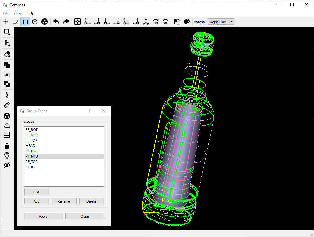
Figure 2: Container imported using STEP interface
The Nogrid software can import the STEP file including all face names. This is very important, because in that case the Nogrid software can connect all faces with the corresponding initial and boundary conditions and run the simulation without any additional user interaction. What does that mean?
Within the Nogrid pointsBlow software all kinds of container walls types are predefined using a unique name. For instance there is a wall type using the name PLUG. This PLUG type is connected with a set process data, which defines the initial position and temperature, the thermal conditions, the movement and the times for activating and deactivating. If Nogrid pointsBlow imports the STEP file and it finds faces carrying the name PLUG, all the PLUG simulation data are connected to these faces.
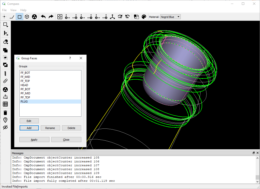
Figure 3: View on the PLUG group
Later during computation the PLUG faces will exactly do what is defined in the PLUG settings data. The PLUG settings data itself can be modified in the Nogrid pointsBlow GUI (Graphical User Interface). Figure 4 shows schematically the process steps that occur during the BB process and it is clear that the PLUG must be in its final position if the gob enters the blank mold and should be removed at IS time "Plunger Up off" shortly before the counter blow is switched on. The User can set the IS machine data easily within the GUI for all wall types and all thermal conditions as well.
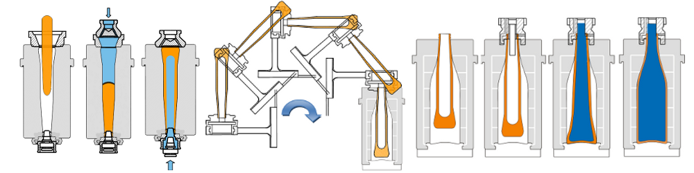
Figure 4: Steps during Blow and Blow process
If the User has decided to investigate a modified geometry, only the geometry needs to be replaced. The simulation data can be reused (or simply copied to a new case, which is done in the software automatically). This is a big advantage of seperating the geometrical data from the simulation data.
Once the 3-D CAD geometry is imported the User can easily select the geometrical dimension of the model. That means the User is able to run the simulation in 2-D (axis-symmetric), 3-D part or full 3-D.
2-D (axis-symmetric) means, the object remains unchanged if it is rotated around an axis. Because the 3-D problem reduces to a 2-D problem in that case (please refer to Figure 7) the computation time is reduced significantly. In the example below the computation time for full 3-D is about 1-2 hours whereas for 2-D it is about 3-5 minutes. Internally the software cuts the 3-D model (which are 3-D faces) by a plane and as a result edges are generated. The edges will inherit all properties from the corresponding face and the edges construct the geometrical border for the 2-D simulation now.
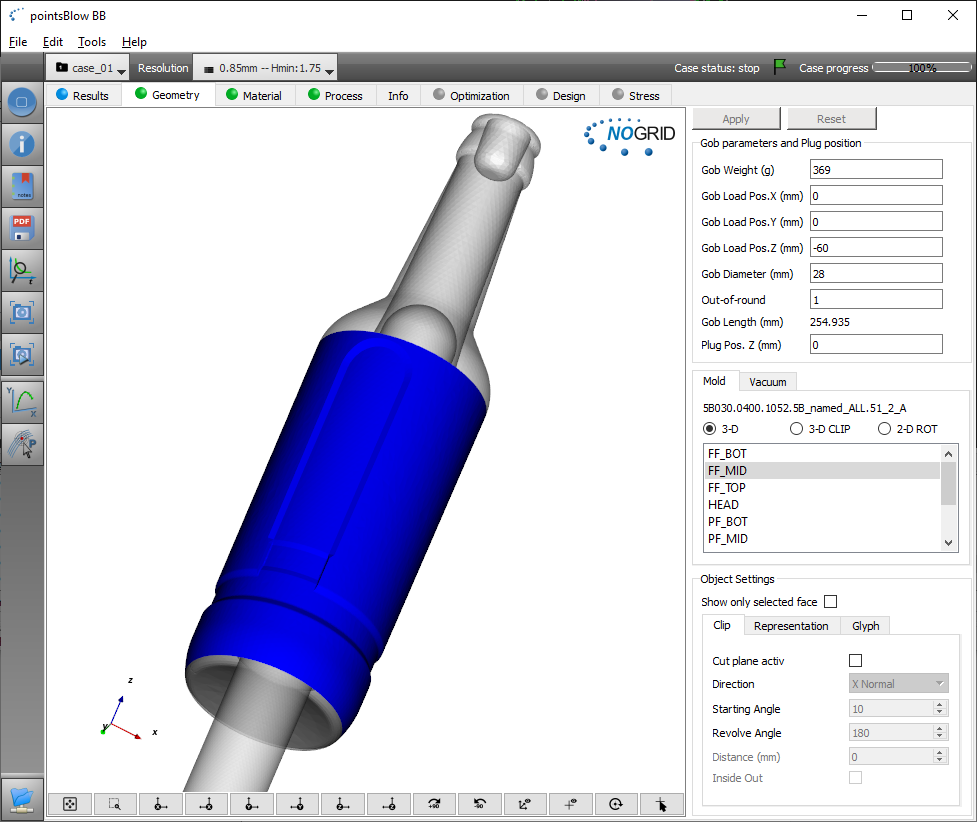
Figure 5: Geometry full 3-D
Without changing the CAD geometry or modifying the simulation conditions the User can easily switch between the different dimensions. In case of the 3-D-part model (see Figure 6) only a part of the 3-D container is computed. In a combo-box it is possible to select different rotating angles from 180° (half model) to the smallest angle of 60° (1/5 model). The full 3-D geometry is cut automatically and the cut faces will inherit all properties from the full 3-D faces.
Figure 6 shows the 3-D-part using a cutting angle of 72° and Figure 8 shows the related results.
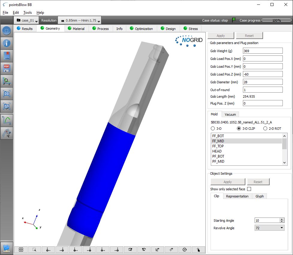
Figure 6: Geometry 3-D clip using angle of 72°

Figure 7: Geometry 2-D (axis-symmetric)
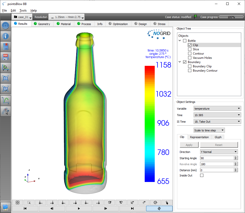
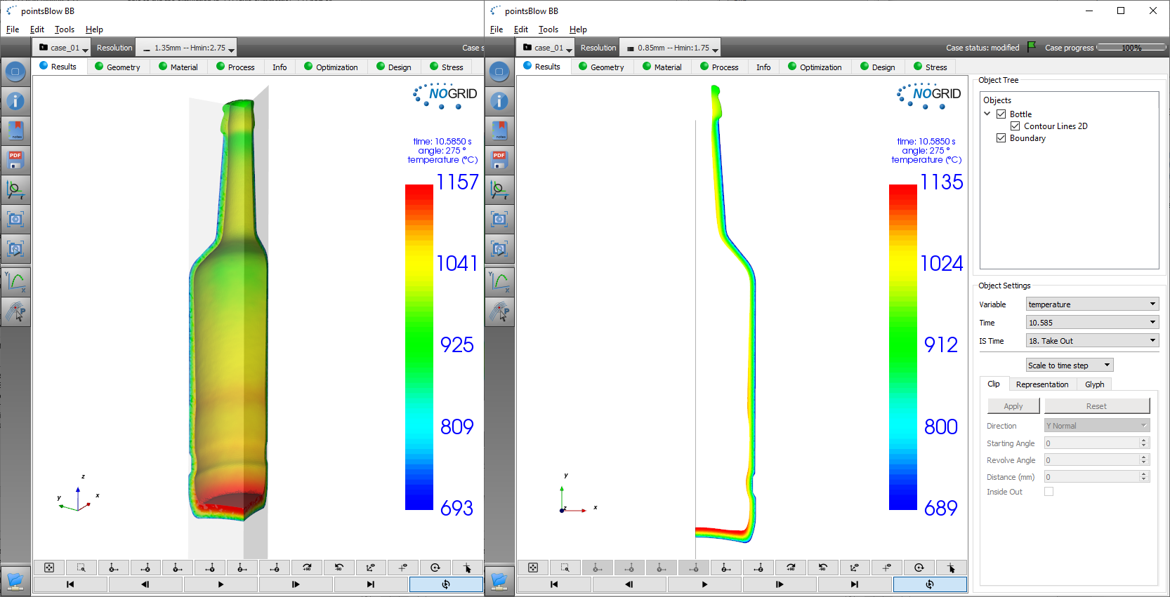
Figure 8: Results 3-D, 3-D-clip and 2-D (axis-symmetric)
A further advantage of separating the geometrical data from the simulation data is that it makes it easy to add additional wall types to the simulation.
For instance in reality a funnel is always used to ensure that the gob falls into the blank mold and not beside. In simulation the funnel walls are usually not required, because the gob position is well defined. But in cases where it is important that the gob is deformed and decelerated by the funnel, the funnel should be added to the CAD geometry. If the name "FUNNEL" appears in the STEP file Nogrid pointsBlow will activate the funnel wall type (see Figure 9), otherwise the type is ignored.
As you can see in Figure 7 or Figure 9 additional faces for the gob are included automatically. These faces represent the shape of the initial gob geometry and the User can modify the shape and its position individually within the GUI. For instance if the User changes the gob weight, the length of the gob will change and if the gob diameter is increased by the User the gob length will decrease correspondingly as well.
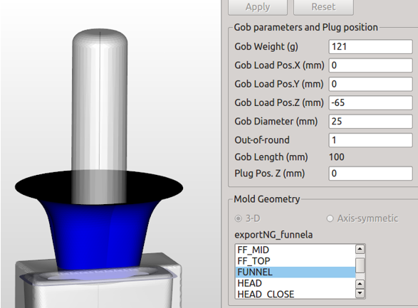
Figure 9: A funnel appears if created in the CAD system
As one can imagine the shape of the bottle can be each real 3-D shape. Also bottles with a handle can be computed. Thus there are no limits regarding bottle design and the User can test and evaluate a certain container without restrictions.
Summary
Nogrid software allows glass container forming processes to be simulated in full 3-D, in 3-D part or in 2-D (axis-symmetric) in a very practicable time for all real container shapes. The User can easily switch between the dimensions without taking care of the underlying geometry. The software will perform all neccessary cuts automatically in the background.
Nogrid's strengths
Particular strengths of NOGRID's fluid flow CFD software are the rapid preprocessing (no fluid grid needs to be generated, only the boundary mesh, inner finite points are generated automatically depending on User setting initially and during computation), and the outstandingly short computation time even for complicated cavities.
As you can see in the image below, the boundary of the geometry still requires a mesh to allow the interior finite points to detect the boundary. The boundary must therefore be meshed and the finite points inside are automatically generated during the simulation controlled by User specifications.
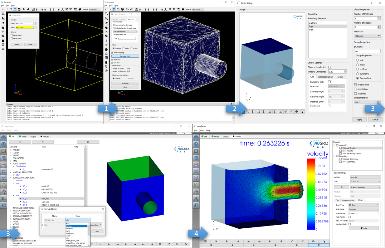
Easy and fast modelling: Build geometry, mesh boundary, setup the case and start computation
What is CFD from NOGRID?
CFD solves the fundamental equations that define the fluid flow process. With CFD software from NOGRID every engineer makes better decisions by predicting, analyzing and controlling fluid flow, heat and mass transfer or chemical reaction. By using NOGRID software for flow modeling you receive information on essential flow characteristics as for example flow distribution. Using it additional to testing and experimentation NOGRID software helps to improve the evaluation of your design – resulting in better construction and operation parameters, increasing planning security and money savings due to faster time to the marketplace for your product or process.
Choose NOGRID
With NOGRID, you choose professional CFD software and services – our aim is helping you to be successful. When you decide to work with NOGRID you choose close cooperation with a dynamic, flat hierarchies-organization. Short information channels result in quick and accurate professional support and service. Our team consists of highly qualified employees, who are experts in fields such as numerical simulation or computational fluid dynamics. Based on our know-how, we are pleased to offer the following services, responding to your individual requirements:
TRAINING
In our two-days training courses you will learn, how to use NOGRID CFD software efficiently. Our technical support team will teach you how to handle and solve different cases.
For more details please refer to Training Courses →
Technical Support
We offer full professional support from the minute you start using our software, by telephone or by email. Contact us, when ever needed.
For more details please refer to Software Support →
Service
Lack of time or resources and other constraints often make outsourcing an attractive solution. We help you with your flow modeling needs. Based on our engineering expertise in this field we offer individual numerical simulation services matching the unique needs of your organization.
For more details please refer to Simulation Services →